The design pressure of the piping system and the leak test pressure. I built-up backpressure should not exceed the overpressure of the PSV in case of conventional type PSV and approximately 50 of total backpressure superimposed plus built-up in case of balanced bellows type ii Mach No.

Relief Valves For Centrifugal Pumps According To Nfpa 20 Fire Protection Specialists
For PSVs discharging to atmosphere this is not required.

. When the vessel is located on the discharge side of the pumps is not protected by relief devices the design pressure shall be determined as the larger of the following criteria Design pressure Differential pressure under normal flow rate design pressure of suction vessel head between the tangential line of the suction vessel and the centerline of the pump impeller. January 24th 2017 Refrigeration Relief Valve. Airmin kgs P 1 valve set pressure psig 11 atmospheric pressure P 1 valve set pressure barg11 1 bar When you know the adjusted system flow coefficient C v0 the adjusted flow C a through the relief valve assembly can be calculated using the following equation.
The PSV discharge piping system should be designed so that the backpressure does not exceed an acceptable value for any pressure-relief device in the system. Hence design should meet following criteria. It is not at all unusual for a PSV discharge line to be significantly larger then the discharge nozzle.
Vi While set pressure cannot exceed the maximum allowable working pressure MAWP for single operating PSV it can exceed the MAWP for one or more PSVs in case of multiple operating PSVs eg. Flange rating은 PSV inlet size가 16이하일 경우 min 300를 적용하고 그 외. Additionally the PSV discharge piping design pressure and test pressure.
The correction factor K N can be calculated the following way. So I have a PSV that has a relief setting at 700 psi natural gas with the discharge piping open to atmosphere. Hi Guys I am checking a piping isometric from our detailed designer.
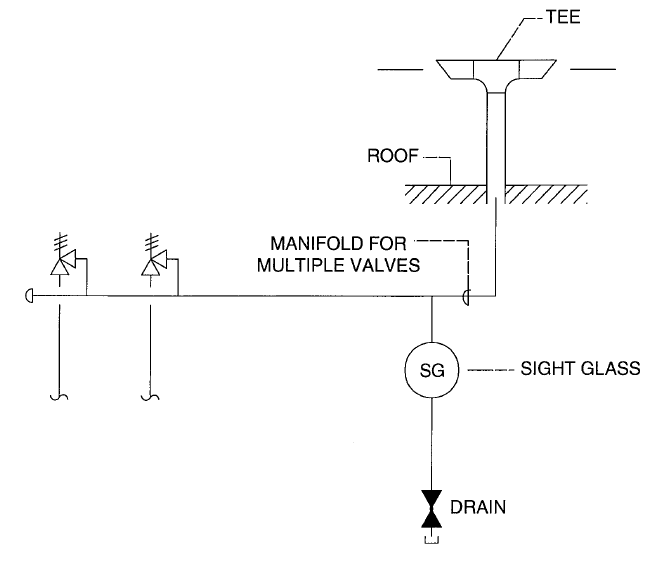
One often overlooked aspect of a relief valve discharge termination piping system is the scenario that was used at the basis of the piping design. Section IV HG-7016 The discharge from safety or safety relief valves shall be so. When a PSV is connected to the flare system the inlet line piping should be equipped with a spool piece to facilitate dismantling as indicated in the sample drawing.
Pressure relief valve are critical to obtaining maximum protection. It is recommended that discharge pipework should rise for steam and gas systems whereas for liquids it should fall. PSV outlet pipe should be designed to avoid excessive backpressure erosional tendency and noise.
Franklin medical group waterbury ct dominican university volleyball team. Section IV HG-7016 A discharge pipe shall be used. PSV discharge Piping Hey guys I need some direction on how to size PSV discharge piping that is open to atmosphere.
I have worked on many projects and in every other project process or client seems to have different philosophies for. We are designing new pressure vessels with design pressure of 1200 kPag with PSVs set at 1200 kPag and flare discharge piping connects to an existing flare system. V flow coefficient for the relief valve C r rated valve capacity lbs.
The line is a PSV discharge to atmosphere. Normally PSV discharge piping would have lower design pressure since its open pipe to flare ie pressure is limited to backpressure from hydraulic losses in the piping and flare system only. Im trying to size the line so that the backpressure from a.
The PSV tail pipe should always slope DOWN to the exit - this is particularly important when the vent stream can condense in the tail pipe. As a dedicated component of the Tank it is required to meet the design criteria of the. Type of reducers used in.
Most designers understand that termination piping must be sized so as to not cause excessive back. Horizontal pipework should have a downward gradient of at least 1 in 100 away from the valve ensuring that any discharge will be self-draining. Design for the worst case scenario.
This information paper details how to design pressure relief device PRD common discharge header piping following the requirements of CSA B51-14 except for Clauses 12227 and 12228 and ASME Section VIII Division I Appendix M. Pressure safety valve required discharge area in the case of steam. Low point drains provided in exit piping can plug up due to corrosion.
All the guidelines given here are very general and may be modified as per specific requirements of any particular project. This applies to all PRD discharge piping that is interconnected with other PRDs through a common discharge header. The PSV is more likely to chatter with a high pressure drop down a small discharge line than it is with the low pressure drop you will get with the large discharge line.
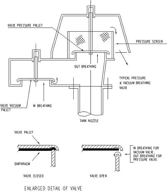
There are 2 PSVs. The materials design fabrication installation and testing shall be in. PSV-2 is designed to protect the Tank and its interconnecting piping.
K N 002764P 1 -1000 003324P 1 -1061 if 10339 P 1 22057 kPa. Safety relief valve and the boiler or on discharge pipes between such valves and the atmosphere. K N 1 if P 1 10339 kPa abs.
Thus in above example maximum set. Its internal cross-sectional area shall be not less than the full area of the valve outlet. Pressure safety valve discharge piping design.
PSV SERIES VALVES Owners Manual Models PSV2S PSV2S2 PSV3S PSV3S2 PSV3SM PSV2SDGR PSV2S2DGR PSV3SDGR PSV3S2DGR PSV3SMDGR CPVC MODEL PVC MODEL Type Size PSV2S PSV2SDGR 2-way 1-12 or 2 Pipe PSV2S2 PSV2S2DGR 2-Way 2 or 2 ½ Pipe PSV3S PSV3SDGR 3-Way 1-12 or 2 Pipe PSV3S2 PSV3S2DGR 3-Way 2 or 2-12 Pipe PSV3SM. Types Design and Construction A pressure relief valve must be capable of operating at all times especially during a period of power failure. It is important to drain any rising discharge pipework.
Design of Boilers and Power Piping Section I PG583 Boiler External Piping The Code Jurisdictional Limits of the boiler external piping systems are shown in Figure PG5831. Using the following flow diagram you can see that PSV-2 on the Tank has a set point equal to that of the Tanks MAWP. Relief Valve Piping System Design Scenario.
Therefore the sole source of power for the pressure relief valve is. It is not advisable to install the PSV below the point where it discharges into the vent. PSV design temperature는 relieving시의 inlet온도와 equipment design temperature중 큰 값이 hot design temperature이고 outlet lowest discharge temperature와 equipment lowest design temperature중 작은 값 이 cold design temperature이다.
Design pressure can be considered in place of MAWP for this purpose as design pressure does not exceed MAWP.
Bn Dg C01c Plant Layout Relief System

Your Opinion On This Sticky Subject Psv Closed System Intergraph Cadworx Analysis
How To Size And Select Your Next Pressure Relief Valve

Piping Engineering How To Design Safety Valve Line Youtube

Relief Valve Relief Header Design Oil Gas Process Engineering

Water Worker Amtrol Steel Water Heater Expansion Tank 15 H X 11 5 W Water Heater Water Heater Expansion Tank Water Heater Expansion Tanks
Atmospheric Termination Of Relief Valve Discharge Piping

The Dos And Don Ts Of Isolating Pressure Relief Valves Valve Magazine
0 comments
Post a Comment